Enhanced Disassembly of Li-Ion Batteries
Winter 2022 - Spring 2022

Overview
For the final eight months of my undergraduate career, I led a group of four in tackling one of the largest challenges in the battery recycling industry. Current recycling solutions lack profitability and entail significant energy costs and waste production. Direct recycling, a low impact and high material-yield process, is not currently employed due to challenges in automatically disassembling a variety of cells. My capstone project proposes a novel direct recycling process that integrates machine learning with state-of-the-art methods to disassemble the three most common types of lithium-ion cells. At the cumulative capstone symposium, we received outstanding feedback, leading to our poster winning a program-wide award.

This video outlines the technical aspects of the project, along with the design process.
Extension
In pursuit of creating a full proof-of-concept, the next step was to model the flow of the entire process. The main goals of modelling the disassembly line were to show which specific equipment units would be used, as well as how the cells would flow between operations. Details on specific equipment models, pipe sizes, component designs, and methods of data collection will be soon to come.

Step 1
The salt water bath has an elevator mechanism for batch immersion, including a conveyor at the base. This allows for discharged cells to be transferred onto the adjacent belt conveyors, which then load the drying trays.
Design considerations & future steps
plc based timer to control elevator
add thermocouples for temperature control
add conductivity probes for salt concentration
add line for water outflow (assuming maintenance time period → most debris exits from the water drainage)

Step 2
Once the drying trays have been loaded, a robotic arm equipped with a fork attachment will transfer the trays into the two ovens.
Design considerations & future steps
can experiment with distance between “shelves” to accommodate larger battery dimensions
3200 cells per batch from saltwater discharging
assume all cells are prismatic (356902 mm3 per cell (biggest)
add 20% safety factor = 1.37 m3)

Step 3
Will add a mechanism to unload the batteries from the trays and arrange the cells in a single file line. Cells will pass under the camera where they are tagged by cell type and dimensions are measured. Orientation will be corrected by a robotic arm before passing into the CNC machine. Specific attachment to fix orientation will be designed.
Design considerations & future steps
sloped bin to collect batteries from oven
video camera with computer for operation
try a series of 3 cameras to capture from sides and top view → gives a more accurate estimate
tagging certain vertices based on key points of the battery
interface with robotic arm to correct orientation
assume wireless integration with CNC cutting (using STEP or gcode files)

Step 4
Cells pass one-by-one into the CNC machine and a universal clamp secures them. A cutting sequence will then be loaded based on their type.
Design considerations & future steps
design universal clamp or suggest jig designs
maybe clamps to come out from the side
add pressure sensor so when clamps contact battery they know how hard to clamp
cylindrical cell press that retracts based on cut
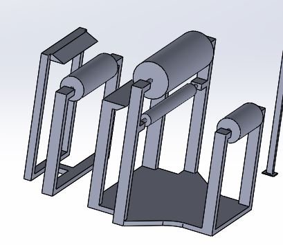
Step 6
Pouch and prismatic electrode complexes will enter a staircase conveyor that will load them into the electrode stripper shown to the right. Cylindrical electrode complexes will be placed as a spool onto the roller mechanism.
Design considerations & future steps
vertical design where a sheet passes through a series of rollers and cutters
can have a bin for cathode, anode, separator
classic roller for cylindrical cells
split conveyor based on camera tagging for different cell types
forklifts to carry around bins
instead of blades that move in a circular path → can also have horizontal movement
some rubber or gasket material to connect from blade base to collection tubing
if the materials have high friction and electrode is getting caught, can use water tubing to wash the material into the bins
Step 5
When exiting the CNC machine, a robotic arm with a specialized attachment will remove the housing and place the exposed electrode complex on the conveyor.
Design considerations & future steps
will design a pull-apart jig that uses the measurement data from Step 3 to identify the separation point on the housing
another piece to remove the electrode complex and place on the conveyor belt